CONSTRUCTION GUIDE
AVRO ARROW
(CONTEST VERSION)
Copyright, Bill Jones, 2004
SASKATOON, Saskatchewan
This is a work in progress, so there are a couple of rough areas ( Ill point out those that Im aware of) and the info was assembled in a hurry. Many changes were made, so I hope that I included all the right files. This will do for you to practice on till I have all the bumps worked out in a future version.
You may find it helpful to view a "build thread" that I did during design, located at:

Cardmodels.net Forum Index
While youre there, check out the tons of interesting stuff on all kind of paper models.
PRINT:
If you build this model, I would love to have your comments.
E-mail me at:
billjones@shaw.ca with "Arrow" in the subject line.
MATERIAL
This is what I used for construction material. (If you use material of different weight or thickness, you may have to make some adjustments)
Normal paper = 20# bond (75g/m2)
Cardstock = 110# cardstock (199g/m2)
Heavy card = approx 0.5 mm thick cardboard
The parts for heavy card may be printed directly on the card, or on other material and then laminated to the heavier material. If you are laminating, I found that the thin material should be glued to both sides of the heavier material to reduce warping. I printed the parts on cardstock and laminated to both sides of .5mm heavy card. It seemed to work OK.
FORMERS: Cardstock laminated to both sides of heavy card.
#1, 2 and 10 are used as is, (no joining strip applied)
#3, 5, 6, 7, 8, and 9 are wrapped with a long, " (7mm) wide strip of cardstock. Just glue to the former, centered and wrapped as tight as possible.(fig x)
#4 is wrapped with two layers of cardstock, but glued flush to the back of the former. (#4 glues directly onto #5)
#5
Trim a bit of the joining strip from the front, top and bottom, so that #4 fits flush, at the indicated place.
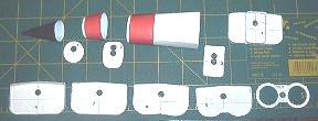
#6
A strip of heavy card is edge glued to the back of #6, along the indicated line. (Should be about 1mm lower than the top of the former, the thickness of your wing frame material, plus skin thickness)
Trim the back of the joining strip, along the top of the former.
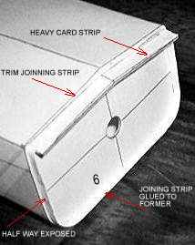
fig x
Holes are punched in the center of the formers, so that a rod or dowel may be inserted. This makes it easier to handle and adjust the formers during initial installation, and in the alignment of the fuselage sections during assembly.
FUSELAGE SECTIONS
Roll the nose cone and cockpit section and form as close as possible to the final shape, then glue using strips of thin paper. Install a joining strip (thin paper) in the smaller end of section (1-2) and section (2-4), about 1/8" (3mm) exposed. Let these parts dry, then assemble section (1-2) to the nose. (join in the cone should go to the bottom, join in section (1-2) & (2-4) is at the top). Let dry, then install former #1. Insert the formers only as far as necessary to produce a smooth shape. Next, add section (2-4) to the assembly, with the join at the top. Let dry. Install former #2 and #3, again only as far as required; #3 should be about " from the large end of section (2-4) Install the #4 & #5 former assembly to complete the front section.
(Note: sections can be fitted together easier, if the joining strip of the former part, is rolled inward, slightly.)
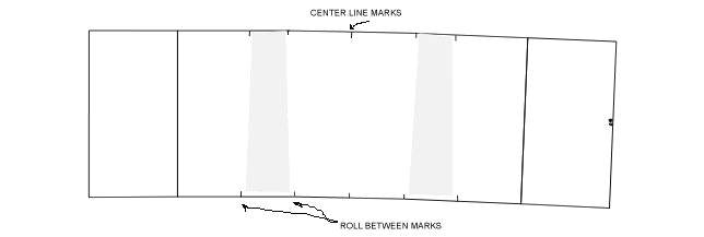
Generally, the fuselage sections are formed into a rounded rectangular shape. Score solid lines, lightly, and make a sharp bend. Tick marks along the edge of the piece are a guide for aligning and rolling. The center mark indicates the center of the part, and should be aligned to the center tick mark of the next section, during assembly. The other tick marks indicate a smooth roll. Align the marks over the square edge of a table and make a gentle crease. The paper can be rolled by then drawing the part over the table edge, from one crease to the other. A long dowel (knitting needle), of various sizes may then be used to continue the roll to a smaller radius. Continue shaping until the part will retain the final shape. Make joining strips from cardstock, about " wide (12mm), and scored up the center. When dry, insert dowel into one of the two formers for that section. Insert former, at an angle, and gradually square it up, forming the skin around it as you go. Do this with both formers before any gluing is done. When you are satisfied that everything is going to fit, the higher number former can be glued in.
(Note: sections are labeled "(6-7)", for example, so that particular section will have former #6 in the front end and former #7 in the other end.)
The former final position should have the joining strip, half way protruding from the section part, with the former center line aligned to the center tick mark of the fuselage section part.
WINGS
Wing frames and rib parts were printed directly on the heavy card, without laminating. Each rib consists of two parts. (black number and red number) The ribs taper to a very narrow section at the trailing edge. I found it easier to make the long, straight cuts first, with straight edge and knife, leaving scrap material attached at either end. Then make the long curved cut(I used scissors), and finally trim both ends. Depth of the notches should equal the thickness of the heavy card.
Wing frame part, printed side up: roll up, inboard half of leading edge tapered section; score and bend up, the outboard half of the leading edge. Cut notches in the leading edge (width of 2 times heavy card thickness) Cut the wing notch (Dog Tooth) from leading edge to flaps. Narrow strip remains attached to the frame part. Wing assembly is best done on a flat, hard surface.
Glue the black number ribs to the frame part on the indicated lines. Minor adjustments can be made as the glue dries, somewhat. Glue the matching red number rib to the black one. Rib #1 should angle slightly, towards the wingtip; all others should be perpendicular to the frame part.
Glue the flap hinge part to the frame part at the indicated position. Should butt up to the rib ends(may have to trim rib ends)
Glue the hinge spacer part on top of this. Should fit into the notches on the end of the ribs.
You now have two narrow strips of heavy card to form the wing notch(Dog tooth) These are glued to each other and centered on the ribs of the inner and out wing sections. Completed wing frame assembly should dry completely before gluing on the skins.
(Note: Wing assembly should be flat on the top, but is curved and tapered on the bottom, which makes it hard to apply pressure evenly during drying. I used a "SPONGE SANDWICH". Lay assembly on a flat hard surface, printed side up. Cover with a layer of sponge or foam rubber. Place a flat hard board on top of this. Set a weight or heavy book(s) on top of the whole pile, and let dry.)
Apply skins: Dry fit and gently form skin parts to the frame part, before gluing. Pay particular attention to a good fit at the leading edge, along the Dogtooth and around the flap area. The other edges are easier to fudge, er..ahadjust, if you have to. When both skins have been attached, apply the "SPONGE SANDWICH"
After skinning, the flaps may need to be trimmed slightly, so they move freely, without catching or binding. Use a straight edge and knife to carefully shave around the edges. The outer skin can be gently rolled over the edge of the inner heavy card, using a knitting needle or other suitable tool. Color the edges.
Wing assemblies glue to the top and sides of the fuselage section. You may need to shim up the connection at the front of the wing frame. Just add required thickness between the top of the fuselage and the wing frame, to give a smooth joint from fuselage section (5-6) to the top of the wing assembly. Cut a narrow notch at the back, at the engine cowl marking, to allow former #10 to fit wing frame.
TAIL
Laminate the three pieces together, with the hinge part in the center. Let dry, then sand and round the leading edge. Apply skin. Trim rudder using same method as for the flaps. Dry completely under pressure.(books)
EXHAUST
This is one of those "rough areas" that I mentioned earlier. The engine tube was originally supposed to extend through former #10, and glue to #9. However, a "quick fix" had to be made here.
Roll exhaust cone section and engine tube parts. Place cone, larger end down, on a flat surface. Glue engine tube into the cone, with both sitting squarely on the flat surface. When dry, just trim off the excess tube,(Its way too long) and butt glue to former #10. (join in the cone goes to the bottom) Roll engine cowls and glue to the indicated position on top of the wing. Should extend over former #10, and butt to exhaust cone. I included enough parts for two sets, incase disaster strikes! J
INTAKES
Construct part with same methods as fuselage section parts. The front, top and bottom, of the joiner strip, on former #5, must be notched to allow the intake sections to fit up to fuselage section (5-6) Attention to lining up the lettering. Paint the ramp and inside with flat black paint.
CANOPY (windshield to exhaust cones)
Score frame parts down the center and bend slightly. (to fit the top of the fuselage sections)
cp frame 1: cut out the long slot before the part is cut from the stock. Glue a piece of thin paper on the bottom of the frame part so that it covers the slot. Finish cutting out the part. (This holds the narrow parts in position) Roll skin part cp1 to final shape using dowels of suitable diameter. Cut out the long slot. Glue skin to frame part with frame inside the skin.
Part cp4, gradually transitions from flat at the front of the window, to semicircular at the back of the part. Score lightly around the triangular windshield section and roll the remainder of the part. Join with thin paper. Glue part to cp frame 1. Continue with cp3 and cp2. Connect the two assemblies with small joining strips. Attention to the angle between the two parts. This should match and fit to the top of the assembled fuselage sections.
You should now have something that looks like a plane.J
.Bill